VERSA-Grid
Building a wall that needs geogrid to reinforce the soil and stabilize your wall?
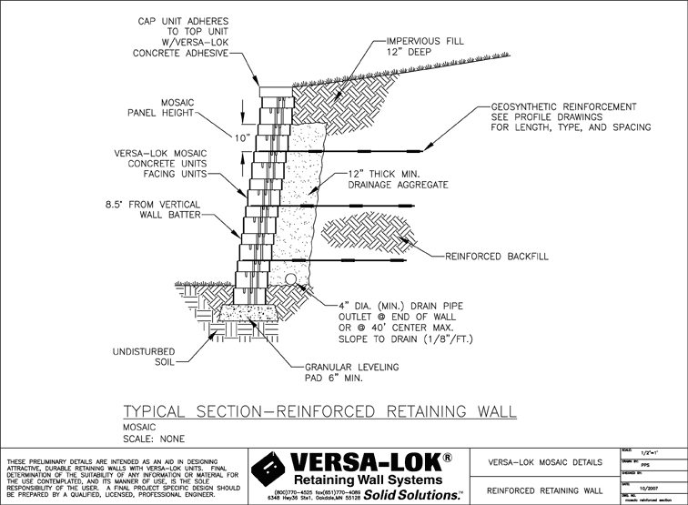
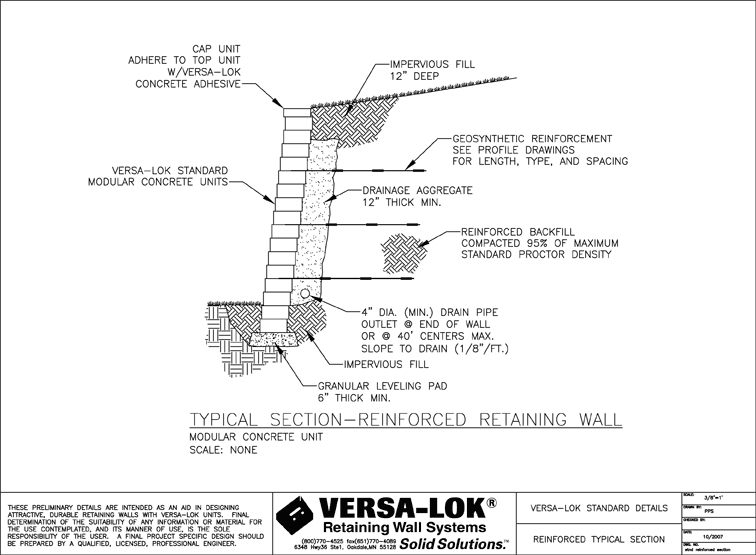
Engineered for durability and long life, VERSA-Grid® geogrid is a high-performance soil reinforcement composed of high-molecular-weight, woven polyester yarns with a polymeric coating. Properly designed VERSA-LOK walls with VERSA-Grid soil reinforcement can be constructed to heights of 50 feet or more.
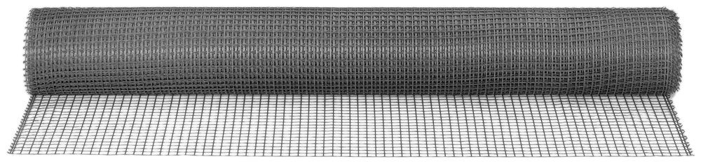
VERSA-Grid is lightweight and easy to install. It’s flexible, with virtually no memory, so it lays flat after being unrolled. Just unroll and make sure the VERSA-Grid is rolled out continuously, perpendicular to the wall face.
VERSA-Grid comes in multiple strength types. VERSA-Grid 3.0, VERSA-Grid 5.0 and VERSA-Grid 8.0 are the strengths commonly used for landscape and commercial walls. These VERSA-Grid strengths are generally available in 6-ft. wide x 150-ft. long rolls (100 sq.yd. per roll). For some residential walls, VERSA-Grid 1.5 is used, but only for walls up to 6 feet tall. It is available in 4-ft. wide by 50-ft long rolls (22 sq.yd. per roll.)
VERSA-Grid Data for Engineers
If you are a licensed professional engineer (P.E.) doing a final wall design, you can download VERSA-Grid data with various VERSA-LOK wall units in a VDF (vendor data file) for use in NCMA's SRWall 4.0 wall engineering design software. See our Engineering page for more information. For VERSA-Grid data in a file format for use in other wall design software or in printed form, please contact VERSA-LOK at 800-770-4525.
Wall Heights that Require Geogrid Soil Reinforcement
Generally, most VERSA-LOK units need geogrid for walls taller than three to four feet. If there are steep slopes near the wall, loading above the wall, tiered walls or poor soils, then even shorter walls may need geogrid. For the maximum, stable unreinforced wall height in the best conditions (gravel soils, no loads, level grades, proper drainage), see the notes for each VERSA-LOK unit type on our Products page.)
Estimating Geogrid Quantities
The length, vertical spacing, number of layers and strength of the geogrids needed will vary with each wall project, depending on wall height, loading, slopes, and soil and water conditions. Retaining walls taller than 3 to 4 feet typically require a qualified professional civil engineer (P.E., licensed in the state of the project) to prepare a project-specific, final wall design that shows the needed geogrid based on actual site conditions. Consult with a local building code official regarding permitting and wall design requirements. VERSA-LOK and local VERSA-LOK representatives can provide contacts for engineers with segmental retaining wall design experience who are licensed in your state.
For preliminary geogrid estimates, your local VERSA-LOK representative can assist in estimating geogrid lengths and quantities. VERSA-LOK’s Solid Solutions Estimating Software can also help in preliminary estimates of geogrid quantities. The Design and Installation Guidelines manual for each type of VERSA-LOK unit also includes VERSA-Grid estimating charts for that unit type, for common site conditions.
How to Install VERSA-Grid Soil Reinforcement
This is basic overview of VERSA-Grid installation portion of wall installation. It is not a complete guide. For product-specific information on wall installation procedures, obtain a copy of the VERSA-LOK Design and Installation Guidelines manuals for the VERSA-LOK unit being used.
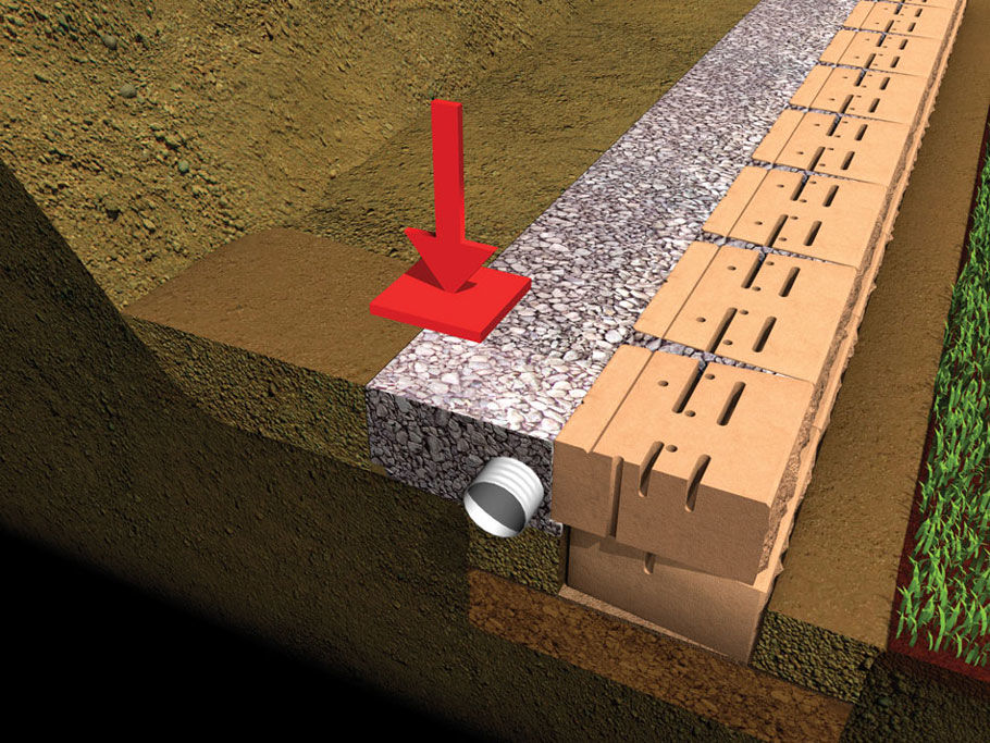
Step 1
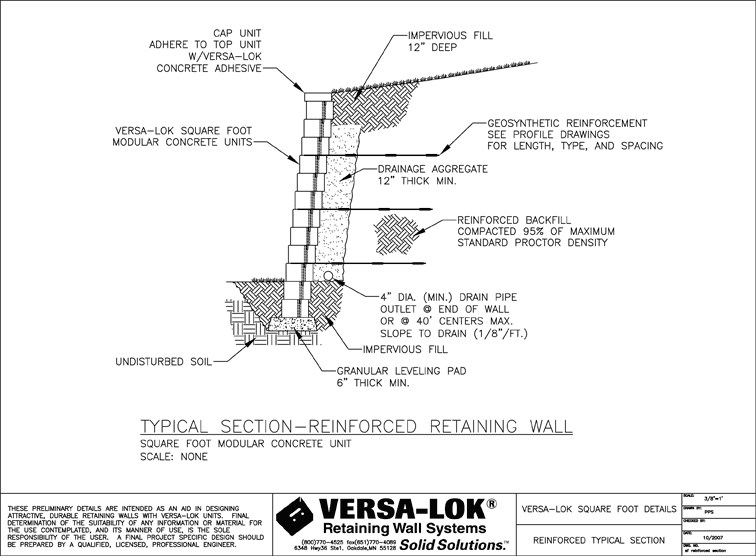
The wall installation, including geogrid installation, should be done in accordance with the project-specific final wall design and specifications, prepared by a qualified, licensed professional engineer (P.E.) and any applicable building codes and standards. Prepare to install VERSA-Grid by placing VERSA-LOK units, backfilling and properly compacting soil fill and drainage aggregate up to the height of the first (lowest) soil-reinforcement layer that is specified on the final, professionally engineered construction drawings (P.E. stamped plans) (Figure 1, below). Several layers (lifts) of soil fill will need to be placed and then compacted to reach the height of the first geogrid layer elevation. Note that the maximum allowable thickness for loose soil lifts, before compacting, varies with type of backfill soil and compaction equipment used.
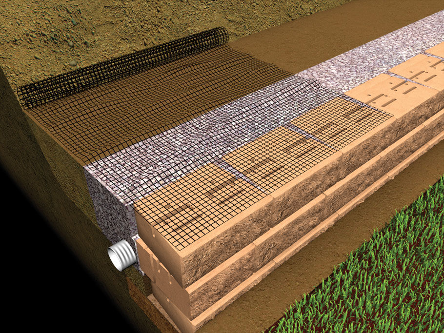
Step 2
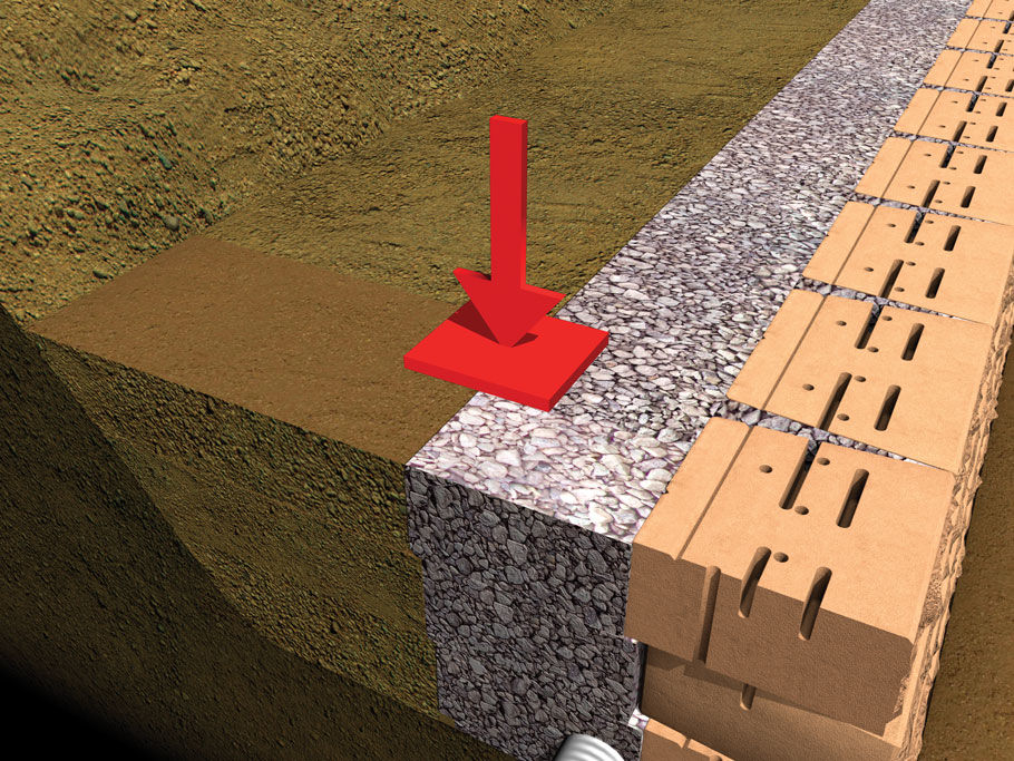
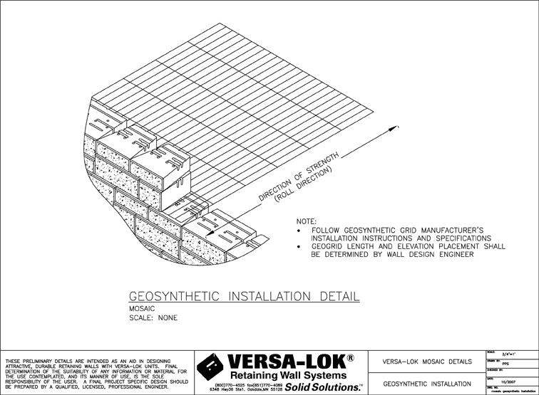
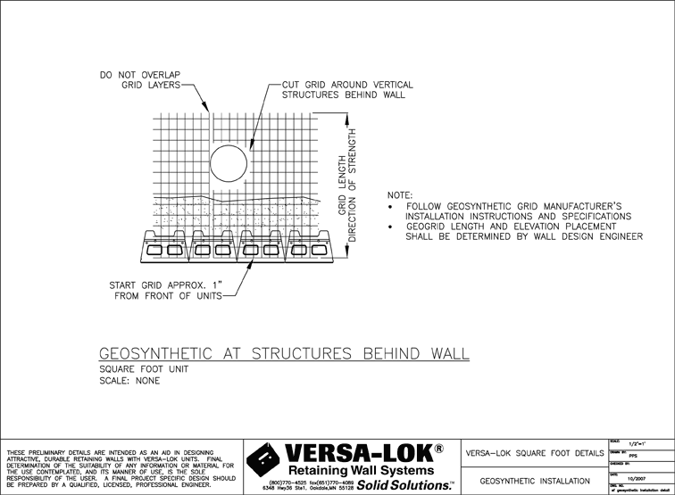
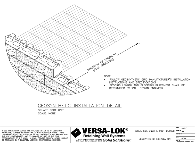
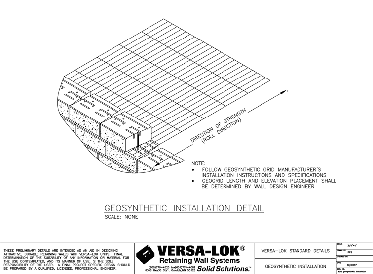
Lay VERSA-Grid on top of the properly compacted backfill, drainage aggregate and VERSA-LOK units by unrolling it perpendicular to the wall. The geogrid strength is in this roll direction. Keep the front edge of the grid one inch behind the front face of the wall, so that the grid completely covers the holes and slots in the VERSA-LOK units (Figure 2, below). Using a scissors or knife, cut to the length shown in the final wall design plans.

Step 3
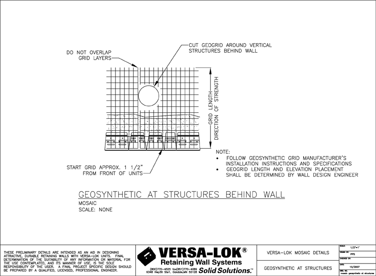
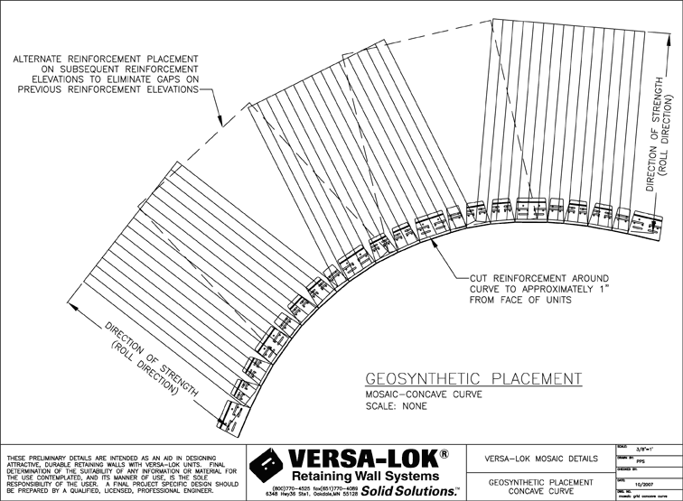
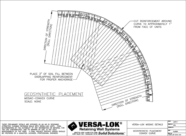
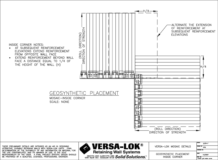
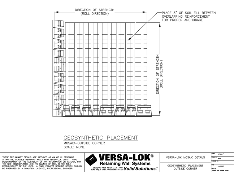
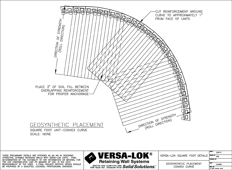
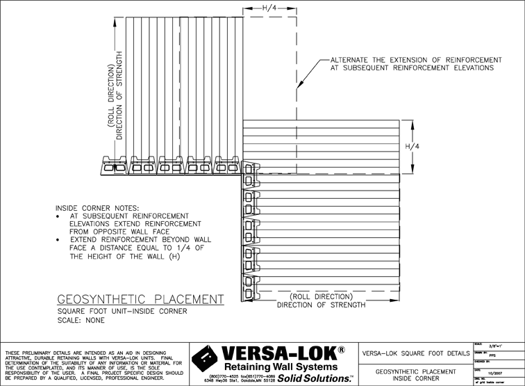
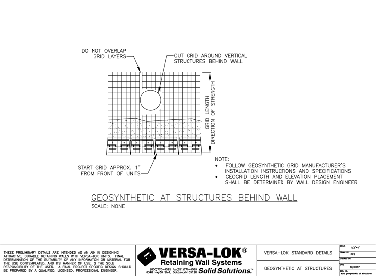
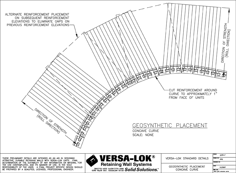
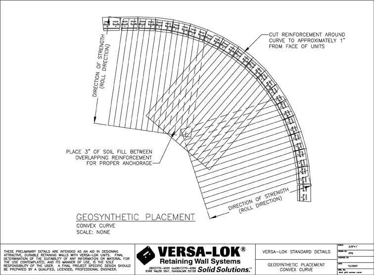
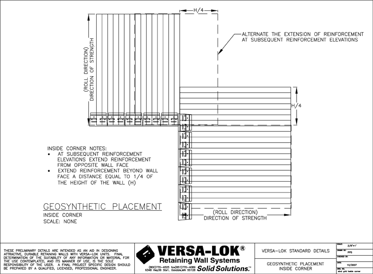
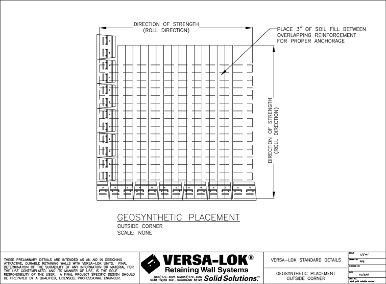
Placing geogrid behind curves and corners requires special layout and overlapping procedures. Never overlap geogrid layers without soil in between the layers; always provide at least three inches of soil fill between overlapping geogrid layers. Slick surfaces of the grid will not hold in place properly when placed directly on top of each other. See illustrations in VERSA-LOK Technical Bulletin #3 for general guidelines for placing VERSA-Grid in curves or corners, and follow the final wall design (P.E. stamped plan) details and recommendations. Questions, needed details and other clarifications should be directed to the final wall design engineer.
Step 4
Correctly position the next course of VERSA-LOK units on top of the grid. Insert two VERSA-TUFF® pins per unit in the upper units. Drive the pins through the grid and into the receiving slots of the lower-course units. Use an extra pin and a mallet to set the pins firmly in the lower-course units.
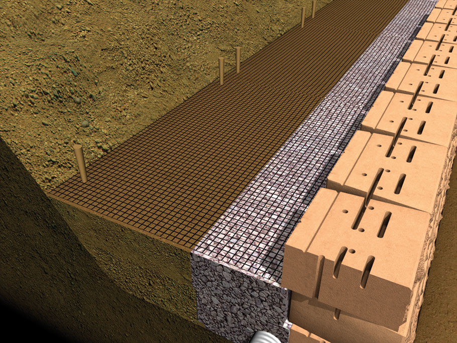
Step 5
Remove slack by pulling the grid backward from the wall face and anchoring at back edge. Place drainage aggregate against back of units and on top of VERSA-Grid. (Figure 3, below).
Step 6
Place and compact the drainage aggregate. Then place and compact soil backfill above the geogrid, starting at the wall units and working back, keeping the geogrid taut to avoid wrinkling.
Step 7
Place a minimum of six inches of soil backfill over the geogrid layer before using any rubber-tired or tracked equipment on top of it. Prevent fill movement and grid damage by driving equipment slowly and turning gradually. Use only hand-operated compaction equipment within three feet of the wall face to avoid excessive equipment loads and possible movement of wall units.
Step 8
Continue placing additional courses, drainage material, compacted soil backfill and VERSA-Grid according to final wall design drawings. Only a few courses of units should be stacked before backfilling. The number of courses that can be stacked without backfilling and the methods for placing additional units varies with the type of VERSA-LOK unit used. See the VERSA-LOK Design and Installation Guidelines manuals for the type of VERSA-LOK unit being installed. Repeat steps 2 through 8.
This is simply a general overview of the grid installation portion of wall construction. See the final wall design (P.E. stamped plans), and see other VERSA-LOK literature for more complete wall installation instructions. Questions, needed details and other clarifications should be directed to the final wall design engineer.